Disclaimer: as many other security researchers approaching IoT, I have a background in computer science and I started to work on these subjects with little knowledge about electronics and often with a “YOLO” approach (blame it on an old colleague of mine 🙂). So, it is definitely possible that many of the things you will read here can be inaccurate or can be done in a much better way, especially with more knowledge in the field. Sorry about that. I take advantage of this disclaimer to add a thing: pay particular attention when you put your hands on electronics, especially when you deal with cheap Chinese devices powered by 220V! Some capacitors can cause serious damages even if the device is not plugged into the electric socket!
In the previous articles (A journey into IoT – Unknown Chinese alarm – Part 1 – Discover components and ports and A journey into IoT – Unknown Chinese alarm – Part 2 – Firmware dump and analysis) we analyzed many aspects of our unknown device. It’s time to have a look at the communications with the sensors (motion sensor and door sensor) and the remote controls.
At the moment we don’t have any information on how they communicate with the smart hub, nor on the frequency they may use. During the first step of our analysis we identified a chip that may be responsible for the communications with the sensors, but we could not find the datasheet. So, we need to understand how it works by reverse engineering radio signals. Users with a little experience in radio hacking will notice that our use case is quite simple and common. By the way, in order to follow the tutorial style of this series of articles and to show the entire reverse engineering process, we will approach it step-by-step as a totally unknown signal, like we do for more complex use cases. A good introductory paper on this topic is the thesis of my colleague Maurizio, from which I took a lot of useful information for this article and that can be downloaded from his GitHub repository.
So, let’s start our analysis from the communications between the remote control and our target device, that are quite interesting from a security perspective.
First, we will try to understand the frequency. To avoid interference, transmission on radio frequencies are regulated by laws, some of them different among countries. It is possible to transmit without licenses only on specific frequencies. The most common ones are:
- 2.4 Ghz (ZigBee, bluetooth and BLE, WiFi, etc.)
- 433 Mhz (mainly used in Europe, Asia, Africa and Oceania)
- 868 Mhz (mainly used in Europe)
- 315 Mhz (mainly used in USA and Asia)
- 915 Mhz (mainly used in USA and Oceania)
- 426 Mhz (mainly used in Asia)
Usually radio devices use a single chip which which use a specific frequency and protocol (or a limited amount of frequencies and protocols) and that takes care of everything (interpretation of the signal, demodulation, transmission). For this kind of analysis we will use a so-called SDR hardware device. SDRs (Software Defined Radios) are hardware devices created to work on different frequencies and to transmit and receive raw radio waves. SRD devices transmit to the PC all the raw information and then all other steps are done via software, allowing complete control.
There are many SDR components on the market, with different prices and features. The cheapest ones are specific models of DVB-T USB devices created to watch digital television channels on a PC, that have inside a chip that can receive a good number of frequencies. Dedicated hardware usually has more features but it is more expensive.
Features that usually impact the price are:
- Frequency range
- Transmission mode (half-duplex, full-duplex, etc.)
- Resolution (ADC & DAC)
- Sensitivity
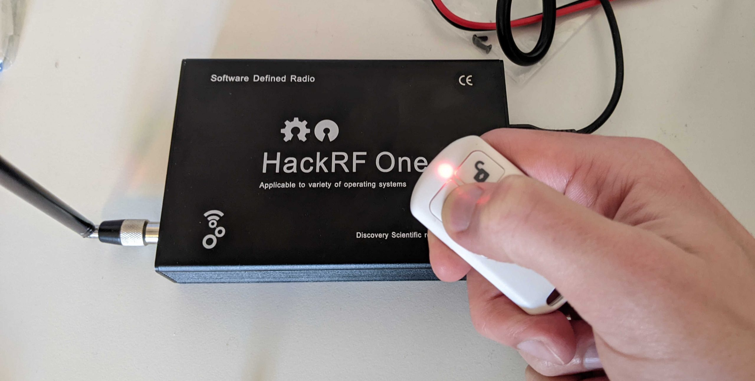
One the most famous SDR devices is the HackRF One by Great Scott Gadgets. The original one costs about 300€ but there are many Chinese clones (about 100€), also due to the fact that it is open hardware. HackRF One is half-duplex, can operate from 1 MHz to 6 GHz with a resolution of 8 bits. Sensitivity is not the best among these devices but it is more than enough for what we need. Great Scott Gadget produces also two telescopic antennas designed to operate in specific frequency ranges. ANT500 operates from 75 MHz to 1 GHz and ANT700 from 300 Mhz to 1100 Mhz. If you know the frequency you are working with, a specific antenna for the right frequency can give better results than telescopic ones.
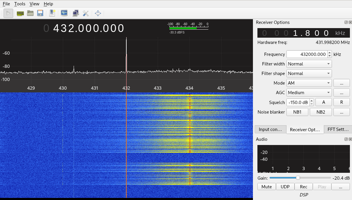
First step we have to do with our SDR device is to find the frequencies at which the sensors and the remote controls work. Many tools can be used for this purpose. One tool of the HackRF One suite name hackrf_sweep is able to scan the entire 0 – 6 GHz range of the HackRF in under one second. At the moment we don’t need that enormous range and we will use a graphical tool name gqrx.
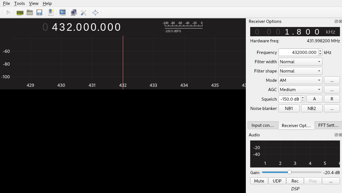
The procedure is simple: we set the frequency of the gqrx tool next to one of the probable frequencies, we start the tool and we push the button of our remote control. If the tool shows a wave, we found the right frequency (pay attention: you may have other devices transmitting on the same frequency or nearby ones, especially on frequencies used by WiFi). Otherwise we configure the tool to the next entry of our common frequency list and then repeat the procedure.
With our alarm, the right frequency was 433Mhz (to be precise 433.92Mhz, closest to 434Mhz in the picture), as we can see from the yellow wave in the picture:
Now that we detected the frequency, we can start analyzing our signal. For this purpose we will use a great tool named Universal Radio Hacker. This tool offers a complete suite for wireless protocol investigation and reverse engineering. It is compatible with many SDRs, including the HackRF One.
After starting the tool we can record our signal using the “Record signal” functionality present in the “File” menu. After setting our SDR device and the correct frequency (433.92M) we can start the recording by clicking on the “Start” button.
Our remote control has 4 buttons. For the moment we will record only the first two, “lock” and “unlock”. We will start with our alarm disarmed and we will push first the “lock” button and then the “unlock” one. We will repeat this procedure three times (for a total of six signals) in order to understand if the signal changes or not on different interactions with the smart alarm. The “Record signal” tool in the right pane shows the recorded waves:
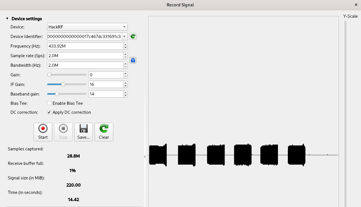
We can save our signal and then close the “Record signal” pop-up. Our signal will be automatically loaded in the Universal Radio Hacker main tool.
Before starting our analysis, some information on how binary data becomes an analog wave and vice versa is necessary. Usually first the binary data is encoded using algorithms that transform each bit in a group of bits, with the purpose of make up for little transmission and timing errors. Then, this encoded input is modulated, with the purpose to create an analog signal from digital information. The reverse process, named demodulation, is the one we are interested in and it works exactly the same, but in reverse order: first we need to demodulate the signal and then decode it.
Explaining in details what modulation is goes beyond the topic of this article but we can think about it as a mechanism to transform a digital sequence of ones and zeros to an analog wave that can be transmitted through an antenna. Fortunately for us, Universal Radio Hacker implements the automatic detection of modulation parameters, but it is always better to check if the result is correct because an error in this phase will completely invalidate the analysis executed on the next steps.
Let’s have a look at the automatic demodulation executed by Universal Radio Hacker, in the “Interpretation” tab:
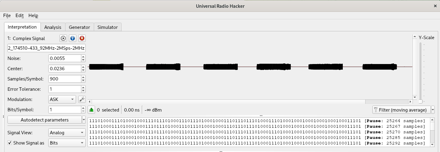
In the left of the picture we can see the modulation type and parameters detected by the tool. According to the tool, the signal is modulated using ASK (Amplitude Shift Keyring). In the top right we have a visual representation of our signal and in the bottom right a binary representation of it. It is important to note that the binary representation at the current phase is not yet the information we are interested in because as we mentioned we have to take care also of the encoding (that we will see in a moment). For now, it can be considered as a digital transformation of an analogical signal, with ‘1’ for ‘high’ and ‘0’ for ‘low’.
The picture contains six blocks, as we clicked on the sequence “lock” and “unlock” three times each. Let’s zoom on the first block:
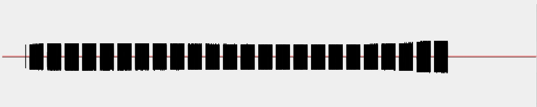
The block is composed by a number of sub-blocks, probably because when we push the button the remote control sends the signal multiple times, till the button is pressed. Let’s zoom on one o the sub-blocks:
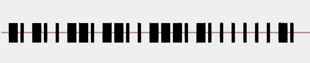
As we can see, we have some portions of the signal with a wave alternated with portions of the signal without a wave. Let’s zoom further on one single block that contains a wave:
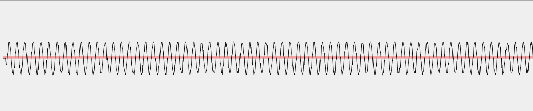
The wave seems to have similar frequency, amplitude and phase all-over the signal and it seems that we simply have a portion of the signal with the wave alternated to a portion of the signal with no wave. Universal Radio Hacker detected this modulation as ASK (Amplitude Shift Keyring) and its guess is correct. More precisely, the modulation is OOK (ON OFF Keyring) that is a variant of ASK.
Modulation algorithms take as input a binary string passed as square wave and convert it to an analog signal. Different modulation algorithms use different parameters of the analog wave to encode binary ‘1’ and binary ‘0’, including amplitude, frequency and phase. ASK uses amplitude, as shown in the following picture from RF Wireless World:
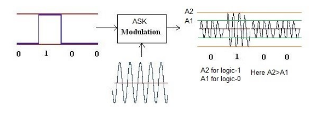
As we can see in the picture, the output analog wave has a bigger amplitude for ‘1’ than for ‘0’. The variant of ASK in use in our signal is OOK, that we can see in the following picture:
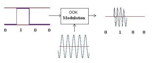
In OOK we have an analog wave only for ‘1’ and no wave for ‘0’.
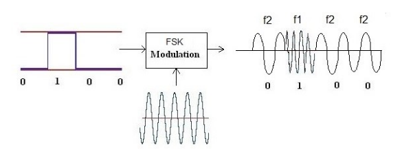
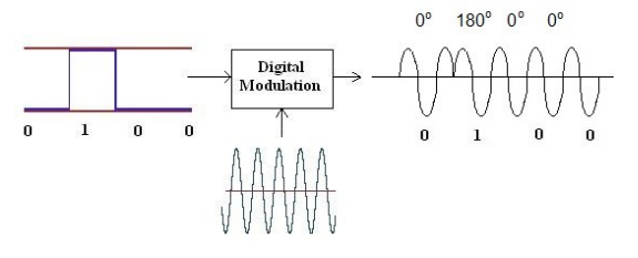
Other modulations commonly used are FSK (Frequency Shift Keyring), based on frequency change, and PSK (Phase Shift Keyring), based on phase change, showed in the following pictures:
Coming back to our signal, we can see the demodulated form of the signal by changing the value of the drop-down menu “Signal View”:
Now, let’s have a look at the right-bottom section that contains the extracted binary value (remember, we have to understand the applied encoding algorithm to retrieve the information the bit stream contains):
1110100011101000100011101110100011101110100010001110111011101000111010001000100010001000100011101 [Pause: 25264 samples]
[... (21 equals entries removed)]
1110100011101000100011101110100011101110100010001110111011101000111010001000100010001000100011101 [Pause: 25279 samples]
11101000111010001000111011101000111011101000100011101110111010001110100010001000100010001000111 [Pause: 1765504 samples]
1110100011101000100011101110100011101110100010001110111011101000111010001000100010001000111010001 [Pause: 25290 samples]
[... (18 equals entries removed)]
1110100011101000100011101110100011101110100010001110111011101000111010001000100010001000111010001 [Pause: 25296 samples]
111010001110100010001110111010001110111010001000111011101110100011101000100010001000100011101 [Pause: 1799065 samples]
1110100011101000100011101110100011101110100010001110111011101000111010001000100010001000100011101 [Pause: 25293 samples]
[... (23 equals entries removed)]
1110100011101000100011101110100011101110100010001110111011101000111010001000100010001000100011101 [Pause: 25317 samples]
11101000111010001000111011101000111011101000100011101110111010001110100010001000100010001000111 [Pause: 1480403 samples]
1110100011101000100011101110100011101110100010001110111011101000111010001000100010001000111010001 [Pause: 25267 samples]
[... (16 equals entries removed)]
1110100011101000100011101110100011101110100010001110111011101000111010001000100010001000111010001 [Pause: 25288 samples]
111010001110100010001110111010001110111010001000111011101110100011101000100010001000100011101 [Pause: 1389952 samples]
1110100011101000100011101110100011101110100010001110111011101000111010001000100010001000100011101 [Pause: 25283 samples]
[... (25 equals entries removed)]
1110100011101000100011101110100011101110100010001110111011101000111010001000100010001000100011101 [Pause: 25282 samples]
11101000111010001000111011101000111011101000100011101110111010001110100010001000100010001000111 [Pause: 1551435 samples]
1110100011101000100011101110100011101110100010001110111011101000111010001000100010001000111010001 [Pause: 25271 samples]
[... (18 equals entries removed)]
1110100011101000100011101110100011101110100010001110111011101000111010001000100010001000111010001 [Pause: 25310 samples]
111010001110100010001110111010001110111010001000111011101110100011101000100010001000100011101 [Pause: 5141308 samples]
Even before analyzing these values, there are many things that we can already see:
- There is a recurring behavior: we have an information sent many times (that depends on the time in which the button was pushed down), then a line with less bits, then another information sent many times and so on (six times).
- The entries with less bits seem anomalous (because they have different number of bits between them) and always end with the number 1. These anomalous entries are the last ones of each sequence, so we can assume that the user released the button in the middle of the sequence or that maybe the tool made some errors with trailing zeros (the tool does not know the number of bits of each line and with OOK there is no difference between zero and absence of transmission).
- Assuming errors in the sequences with less bits, all the other ones on each of the six blocks are equal. Furthermore groups 1-3-5 and 2-4-6 are equal between them (that were respectively “lock” and “unlock” buttons).
- Each line is composed by 97 digits, excluding the anomalous ones.
From these observations we can infer that we have a simple protocol that sends always the same information when each button is pressed, but we will return to this topic after taking care of the encoding.
Now, let’s deal with the encoding. This process with most algorithms encodes one bit of information into multiple bits, in order to make the resulting signal more resilient to transmission and timing errors. Universal Radio Hacker offers a tool to work on encoding in the “Analysis” tab:
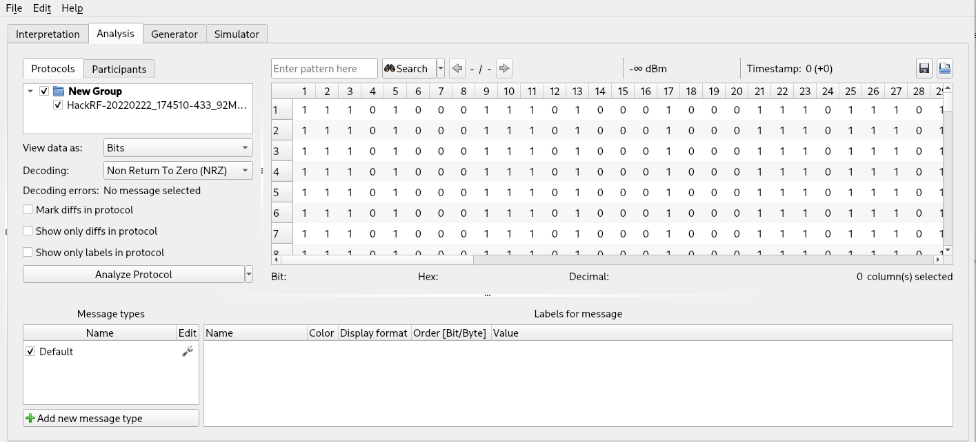
By default, the tool selects the “Non Return To Zero (NRZ)” decoding algorithm, a simple encoding algorithm that code ‘1’ when the demodulated value is High and ‘0’ otherwise, encoding 1 demodulated value to 1 decoded one (we have the same bit string that we saw in the “Interpretation” tab) . This encoding algorithm is rarely used because it has no control mechanisms and does not provide a way to distinguish zeros from “absence of transmission”. It is selected by default because it does not apply any transformation on the value supplied by the previous tool and it can work with any input.
To understand the real encoding algorithm in use, let’s have a look at a single transmission bit string of “lock” button and one of “unlock”, obtained after the demodulation and before applying any decoding algorithm:
- 1110100011101000100011101110100011101110100010001110111011101000111010001000100010001000100011101
- 1110100011101000100011101110100011101110100010001110111011101000111010001000100010001000111010001
As previously observed, we have 97 bits of length. That is a strange number. Probably the correct value is 96 (a multiple of 2) and we may have one leading or trailing bit that may belong to some sort of preamble or trailing sequence.
Next, many remote controls at 433 Mhz send a 24-bit information. If this is the case, we may have an encoding algorithm that encode 1 bit of information to 4 demodulated bits (total 96 bits). So, let’s try to divide our “lock” and “unlock” bit strings into blocks of 4 bits:
- 1110 1000 1110 1000 1000 1110 1110 1000 1110 1110 1000 1000 1110 1110 1110 1000 1110 1000 1000 1000 1000 1000 1000 1110 1
- 1110 1000 1110 1000 1000 1110 1110 1000 1110 1110 1000 1000 1110 1110 1110 1000 1110 1000 1000 1000 1000 1000 1110 1000 1
We can see two different things:
- All the 4-bit blocks are either 1110 or 1000 (not considering the last ‘1’ bit)
- The two bit strings sent with the “lock” and “unlock” commands are very similar (only the last 8 bits, 9 with the trailing 1, are different)
After some research on common encoding algorithms with these features we found the right one: EV1527, a protocol used mostly for simple remote controls. I found a good description of the encoding protocol in the datasheet of a chip that implements it:
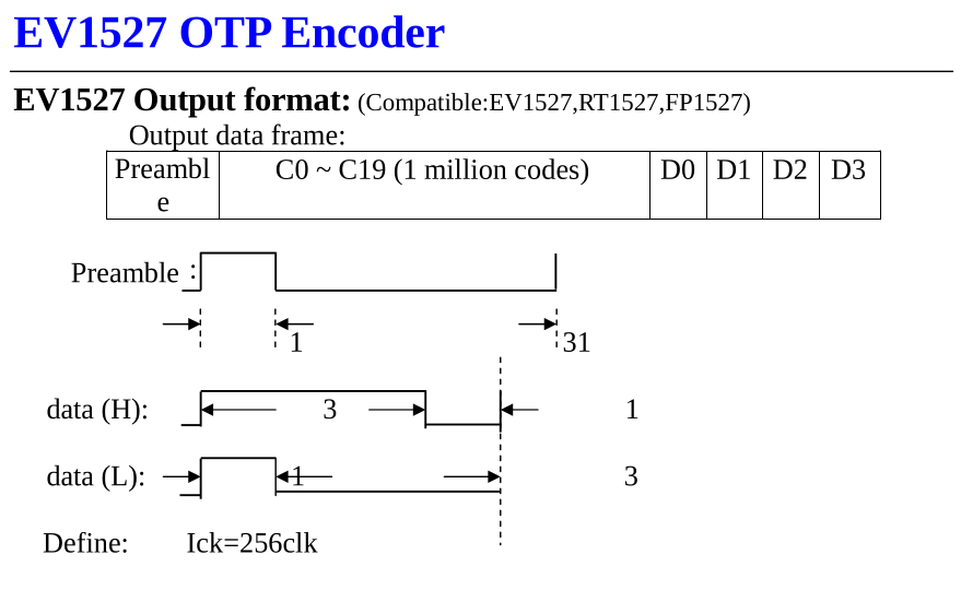
The picture describes the protocol as follows:
- The ‘1’ is defined as three “High” signals followed by one “Low” signal and the ‘0’ is defined as one “High” signal followed by three “Low” signals
- We have a preamble defined as one “High” followed by 31 “Low”
- The data frame is composed by the preamble followed by a 20 bit code (identifier of the remote control) followed by 4 bits (for the buttons of the remote control)
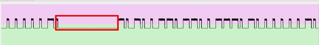
The protocol explains also the last anomalous ‘1’ bit (position 97): it is part of the preamble of the next sequence (one “High” followed by 31 “Low”), erroneously detected as part of the previous sequence by the tool:
Now that we found the encoding algorithm, we can quickly implement it with Universal Radio Hacker, that offers a tool to implement custom decoding algorithms (the “…” entry in the “Decoding” drop-down menu allows to create to encoding algorithms using a comfortable graphical interface).
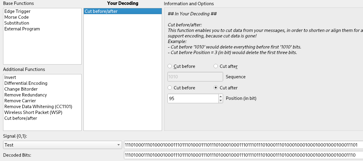
First we simply cut the last bit off (the bit at position 97). It is part of the preamble of the next sequence and it does not contain any information (the “Test” section at the bottom of the tool is very useful during the creation of the encoding routine to see our transformation applied to a bit string):
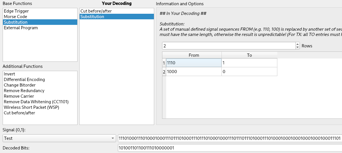
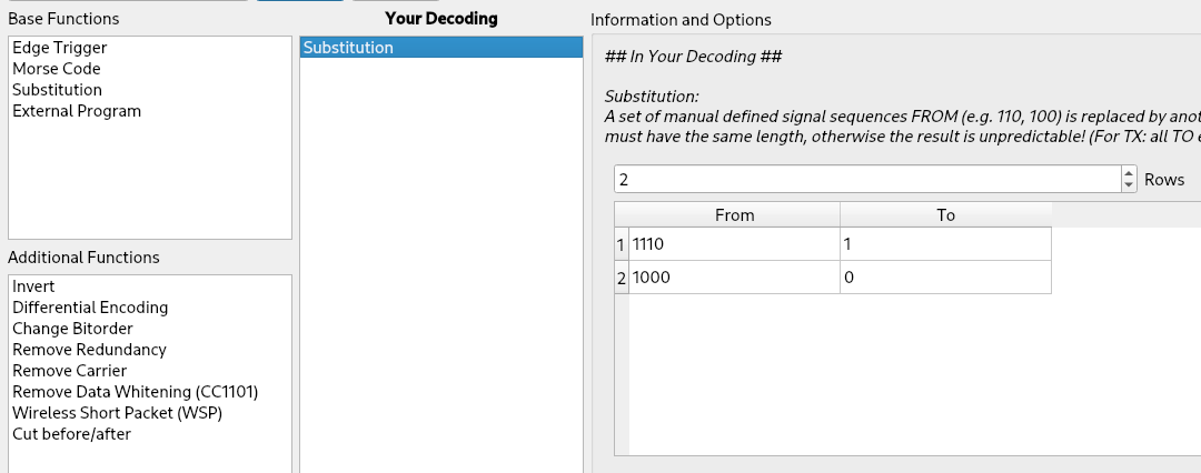
Then we add a “Substitution” entry with 2 rows to replace ‘1110’ to ‘1’ and ‘1000’ to ‘0’:
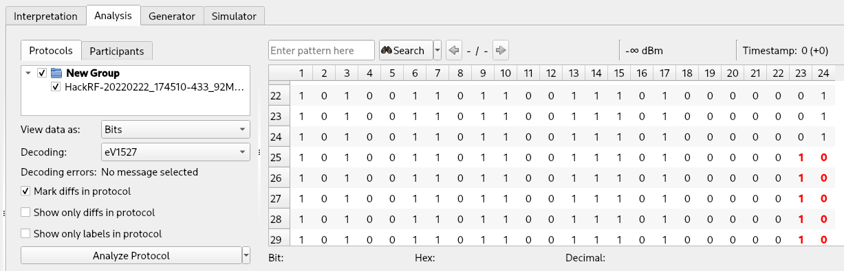
We can save our encoding with the “Save as” button and apply it to our test data. The “Mark diffs in protocol” checkbox is very useful to quickly detect differences among the signals:
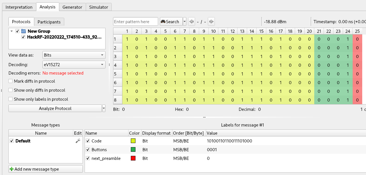
Finally, we can use Universal Radio Hacker labels to color the different sections of our data, simply by selecting the first 20 columns (the code of our remote control), right clicking on the data and selecting “Create label”. Then we can repeat the same procedure for the last 4 columns (the button section). Labels are not useful only for viewing purposes but will be necessary when we will use the “Fuzzer” tool of Universal Radio Hacker (presented later in this article). The result is:
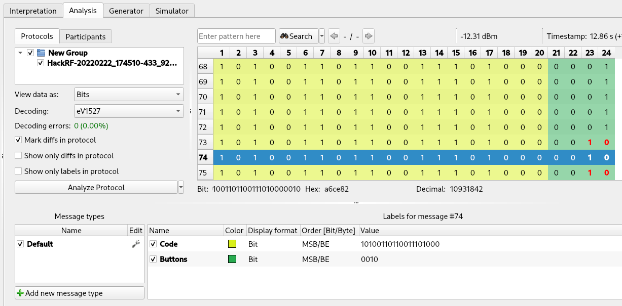
The decoded values for our “lock” and “unlock” buttons are the following:
- 10100110110011101000 0001 (lock)
- 10100110110011101000 0010 (unlock)
Now, let’s talk a little on the security issues the protocol we are analyzing suffers from and then we will try some active attacks using the HackRF One:
- Eavesdropping, spoofing and replay attack: the information sent is always the same and there is no authentication or identification of the device. An attacker can record the signal and replay it to unlock the smart alarm.
- Jamming: it is possible to jam the “lock” signal when the owner pushes the button to activate the alarm to leave his home unprotected.
- Brute-force of button bits: the information sent is made up of 20 bits of remote control identification and 4 bits for the buttons (16 combinations). An attacker can record the signal of any button and execute a brute-force attack aimed at finding the code of the other buttons in a matter of seconds. Furthermore, the remote controls have only 4 buttons but we have 16 potential combinations; maybe we can find some hidden commands 😉
Jamming attacks can be executed mainly in two different forms: noise or repeating. Noise jamming is a simple attack. If you have enough power and you transmit on the same frequency of your target, you can override the signal at the receiver. HackRF One has a tool to jam on arbitrary frequencies on some firmware of the PortaPack (the most supported one at the moment should be the PortaPack Mayhem), an add-on for the HackRF with a display and a battery that allows to execute some tasks with the HackRF One without a notebook. Repeating jamming repeats valid signals (or modifications of them), corrupting or altering the signal received by the receiver. This attack is more complex than the previous one but usually more difficult to detect. Advanced alarm systems can implement some sort of jamming detection and protections, like notify promptly when a jamming attack is going on or use more frequencies to increase the difficulty of a successful jamming attack. Obviously this is not the case of our cheap alarm system but anyway protection against jamming is not simple to implement, especially for wireless alarm systems.
Replay attacks can be executed using the Universal Radio Hacker tool. We can do this operation in two different ways: simply by repeating the recorded signal or by generating a new signal using the data of our analysis, that allows to arbitrarily modify the information sent. To repeat a recorded signal it is only necessary to use the functionality “Replay signal” in the “Interpretation” tab (“Play” button at the left). To generate a new signal using the data of our analysis we can use the “Generator” tool.
If we try to generate a signal using the data obtained using our custom encoder, it will not work because Universal Radio Hacker will encode our data by inverting the substitution of our protocol but it will not add the ‘1’ bit removed by the “Cut before/after” rule of our encoder. But unfortunately that ‘1’ is necessary, because it is the preamble of the next signal. To overcome this issue, we can simply remove the “Cut before/after” rule of our encoder and leave only the substitution rule:
When the rule is removed, a new “0” will appear at the end of each line. This is correct because we are working with OOK modulation. In fact, Universal Radio Hacker divided our signals in different lines based on long sequence of “lows” but with OOK a “low” can be both an absence of signal or a “zero”. Consequently Universal Radio Hacker stops at the last ‘1’ before a sequence of zeros. But there is no difference between a trailing ‘1’ and a trailing ‘1’ followed by three zeros in OOK and consequently after defining the encoding algorithm the tool probably considers three of the “low” of the following preamble as zeros and consequently decodes ‘1000’ to ‘0’.
This trailing ‘0’ will be encoded by the Generator tool of Universal Radio Hacker to ‘1000’ but it is not an issue for us because combined with the pause before the next sequence it will create the next preamble (1 followed by 31 zeros).
The result is the following (I added one more label named “next_preamble” on the last bit):
We can now move to the “Generator” tool and drag and drop the name of our file (on the left) into the table on the right:
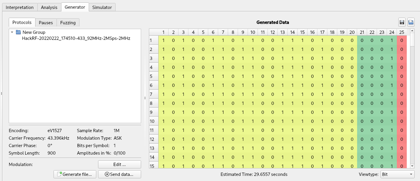
Here if we want we can arbitrarily edit our data and once it is ready we can transmit it by clicking the “Send data” button. And voila, we replicated the “lock” and “unlock” buttons.
Finally, let’s talk about the brute-force of button bits. The “Fuzzing” sub-tab of the “Generator” tool is made for this purpose. To use the fuzzer it is necessary to set the label in the analysis tab. First it is better to remove all entries of the table but one (otherwise it will concatenate the signals we recorded to the fuzzing signals).
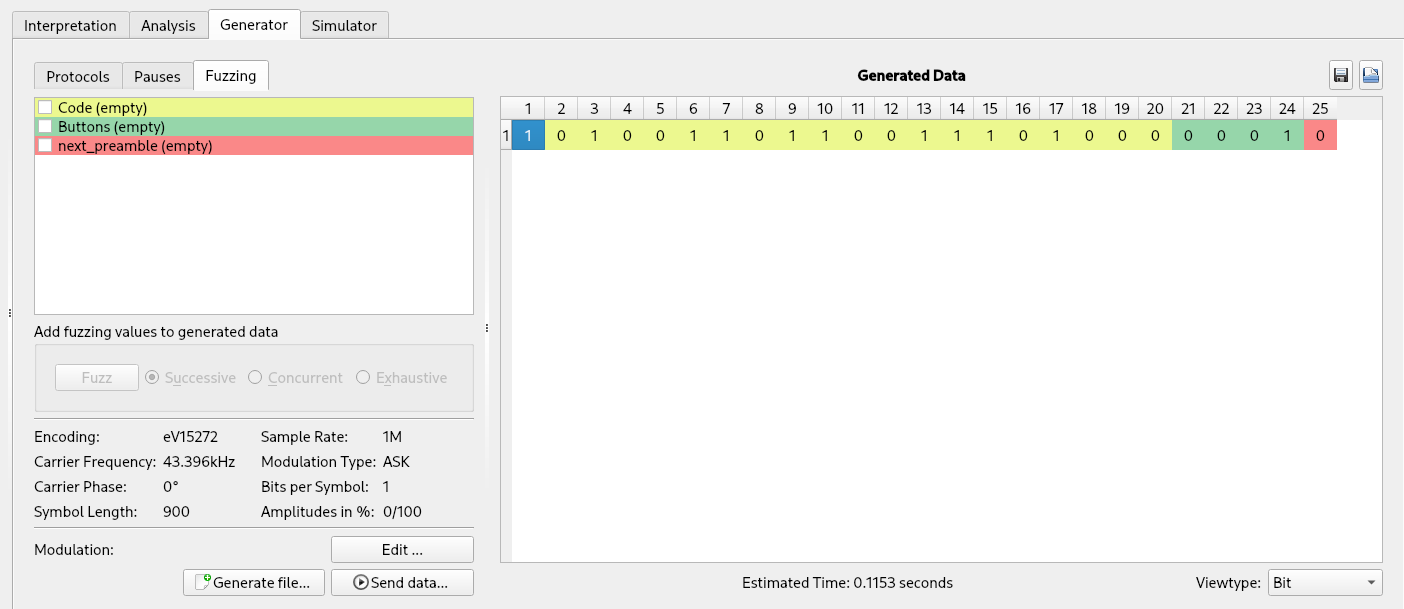
Then by clicking on the only entry we left in the table, its label will appear on the left and it will be possible to configure the attack by right-clicking on the label we want to fuzz (“Buttons” in the current example) and select “Edit fuzzing label”.
Here we can configure our desired fuzzing parameters and then click the “Add to Fuzzed Values” button (by default it fuzzes all combinations of the bits of the label). Then it is better to click on the “Repeat” button on the right of the table to make at least a few copies of each value (a single transmission of an information is not reliable; it is always better to repeat each transmission multiple times).
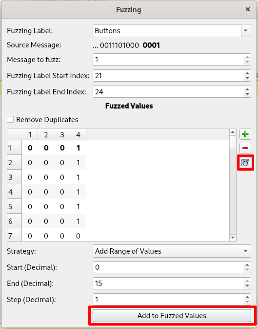
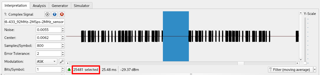
Once configured we can close this popup. Before generating the signals with the fuzzer it is better to change one configuration of the generator tool. By default the fuzzer inserts a pause (no transmission) between each generated signals of the sum of the time of 1 million of samples. This distance is way too large than the distance of the signals emitted by the remote control and the resulting signal may not be recognized by the receiver. I changed that value with one similar to the original recorded track (for me 26K). That value can be changed in “Edit” -> “Option” -> “Generation”. The estimation of the number of samples between signals in the original track can be retrieved by selecting the original pause in the “Interpretation” tool and looking at the number of samples below the wave:
After these configurations, the generation of the samples can be executed by enabling the label we want to fuzz (“Buttons” in our example), click on “Fuzz” and send the attack with the “Send data” button.
On our alarm it worked like a charm and it found all the four buttons signals. Unfortunately, there wasn’t any bonus command other than the four configured on the remote control. 🙂
The analyzed signals were very simple, but Universal Radio Hacker can handle also more complex one, like protocols with several states and challenge-response mechanisms. The “Simulator” tool comes in handy in these situations, allowing complex manipulation of the signals.
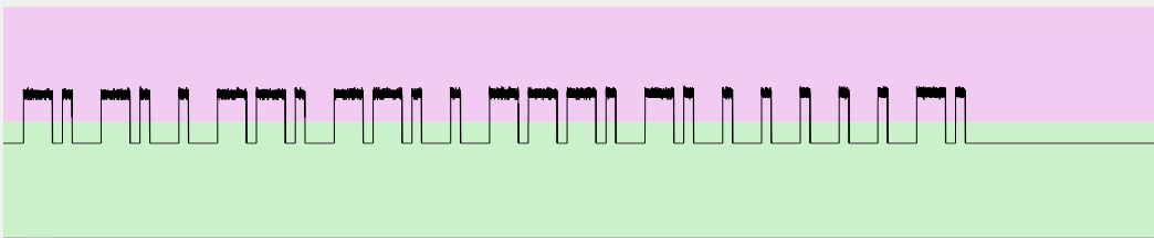
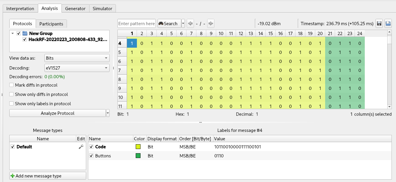
Speaking of the communications between the sensors (motion sensor and door sensor) and our target device, it worked in exactly the same way. They have a different code (first 20 bits) and ‘0110’ in the last 4 bits. Both the code and buttons bit string is checked by the receiver and signals with incorrect information are discarded by the target device. As an example, this is the recording of the motion sensor after the same reversing process executed for the remote control:
The simple protocol analyzed for the remote controls and used also by the sensors exposes the system to another issue. The sensors transmit only when an event occurs (the door is open or something moves in front of the motion sensor). Consequently if an attacker power-offs/breaks/destroys a sensor, the smart hub has no way of noticing this and raise an alarm. Yes, for a cost of 30$ the alarm has more than enough features, but definitely not implemented securely (and if you think that more costly alarms work always differently, you are wrong…).
For this article, that’s all. Our smart alarm employs a very simple wireless protocol to receive signals from remote controls and from sensors but it gave us a good opportunity to go a little more in depth in the analysis of unknown radio signals using the Universal Radio Hacker tool. More complex protocols like ZigBee implement security features and require a different approach to the analysis. Maybe we will see them in another post.
Cheers!