Intro
In our previous article Fault Injection – Down the Rabbit Hole in this series, we have seen how hardware fault injection attacks often allow us to have effects that we can interpret and predict, and how the concept of “skipping an instruction” is fundamentally flawed. Based on the results of our experiments and on some further insights, however, we did not find any instructions that would allow us to flip a single bit, but rather “groups” of bits.
When talking about glitches and fault injection, a theoretical hardware is often hypothesized that, due to its speed and precision, would allow to perform a glitch that affects a single bit, but this model is considered an unattainable unicorn. Always with the aim of trying to better understand how glitching works, I decided to start “looking for a unicorn”, and check if this type of attack is feasible in pratice.
Hardware setup
As in the previous article, in this case as well we will use voltage glitching, which is accessible with a very limited budget. However, we decided to change our setup, separating the CPU power lines. We therefore provided a stable 3.3V to all power lines with the exception of VDD3P3_CPU and VDD3P3_RTC, which are connected together to another power supply and on which we perform the glitching. This is the setup that is generally used, for example, by LimitedResults in their tests.
We will perform the glitching initially with the lowest possible voltage, which is the situation where the system can boot and execute the code correctly in a continuous manner. This voltage has been identified on our hardware as 2.52V. Lower voltages create “unstable” situations where the processor sometimes boots correctly and sometimes does not. Having a lower voltage also helps us to induce faults more easily, as we will see in this article.

Code
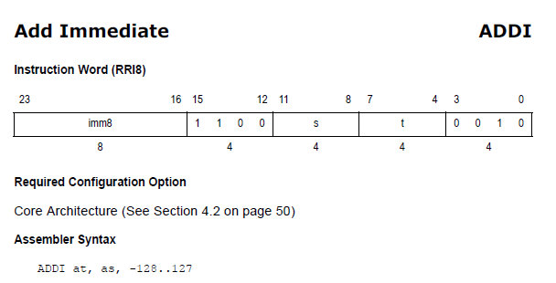
As usual, context is crucial. Most of the assembly code we will use and the basic behaviors are the same we have already worked on in Fault Injection – Down the Rabbit Hole. However, the portion of the code on which we will inject the fault has been changed as follows:
_addi a5, a5, 0x7F
_addi a6, a6, 0x7F
_addi a7, a7, 0x7F
I decided to choose the specific value 0x7F because it is composed of 7 bits set to one. This will allow us to check if we can achieve our goal, which is to modify a single bit at the level of a specific instruction. As we have seen previously, the transition from 1 to 0 is possible with voltage glitching.
For convenience, let’s ignore everything that could allow changing the instructions and focus only on changes on the value of the addition, which essentially is determined by the last 8 bits of the instruction:
Therefore, if our fault succeeds in flipping a single bit, we would then obtain the following possible values:
00111111 - 3f
01011111 - 5f
01101111 - 6f
01110111 - 77
01111011 - 7b
01111101 - 7d
01111110 - 7e
As always, before starting we check with a disassembler that the instructions produced by the compiler are indeed those we expect:
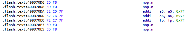
We’re good to go!
Results
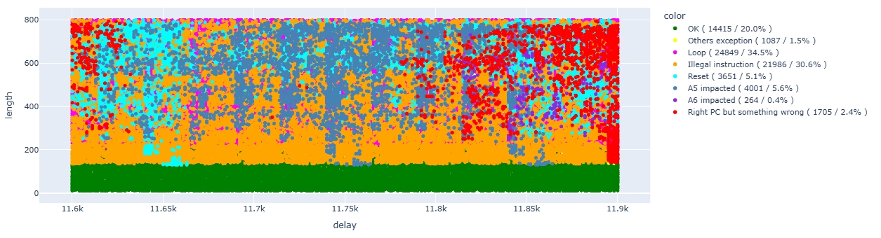
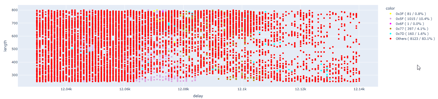
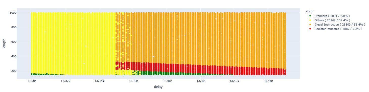
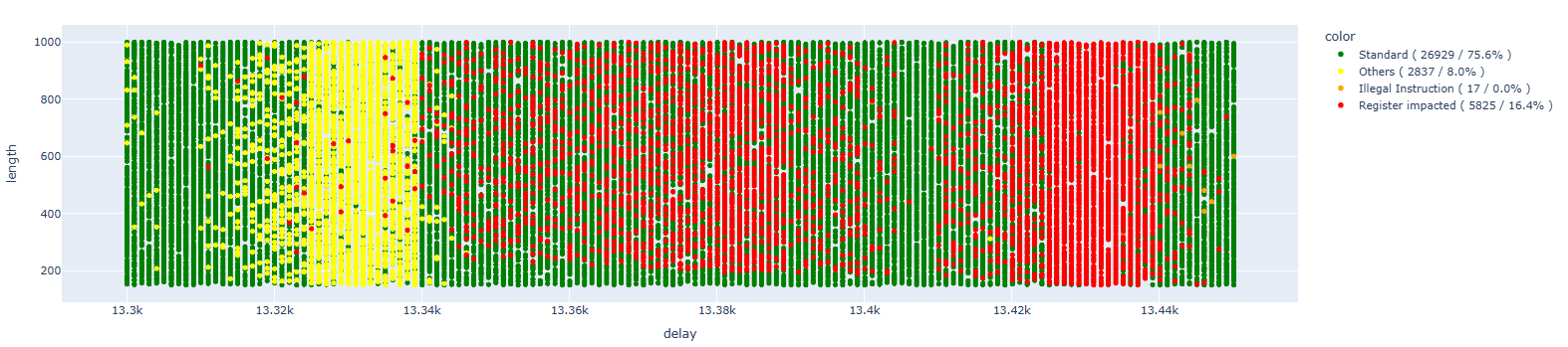
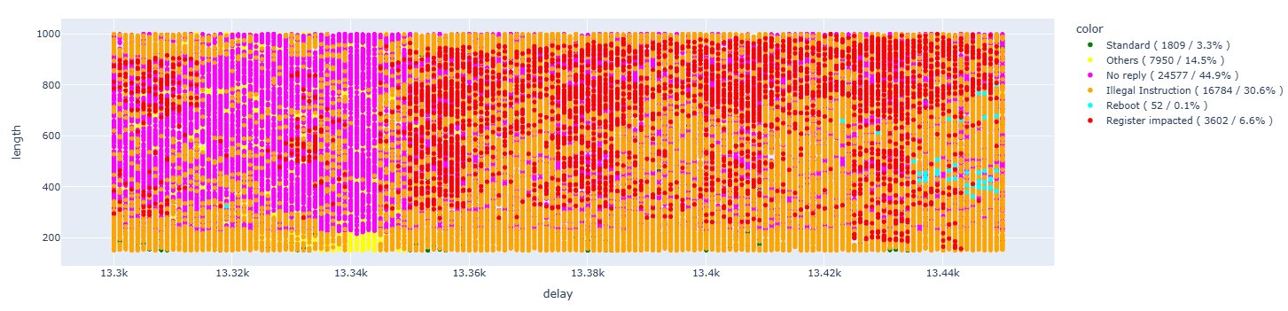
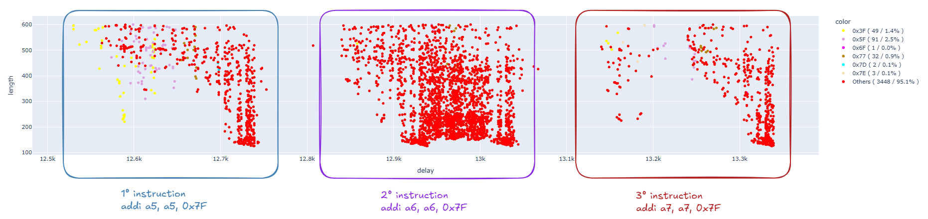
First, we perform a “sweep” using the same configuration and focusing on the same range that we discovered in the analysis performed in the previous article:
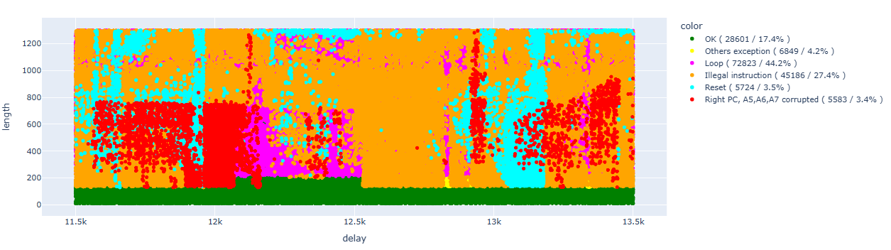
Let’s try to clean up the data a bit so we can focus on the results that interest us:
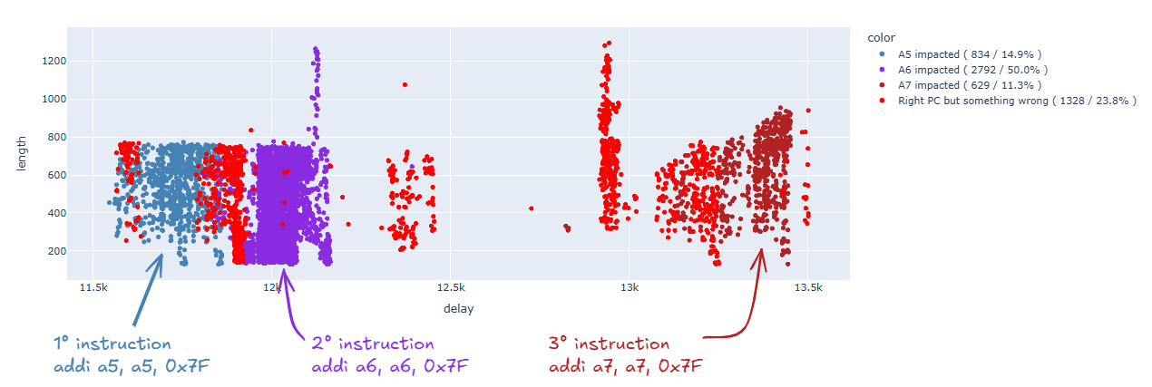
As we already saw in the previous article, we can identify areas of interest for each individual instruction, which will cluster in defined timeframes.
At this point, let’s try to zoom in on the first area, thus focusing on the following instruction:
_addi a5, a5, 0x7F
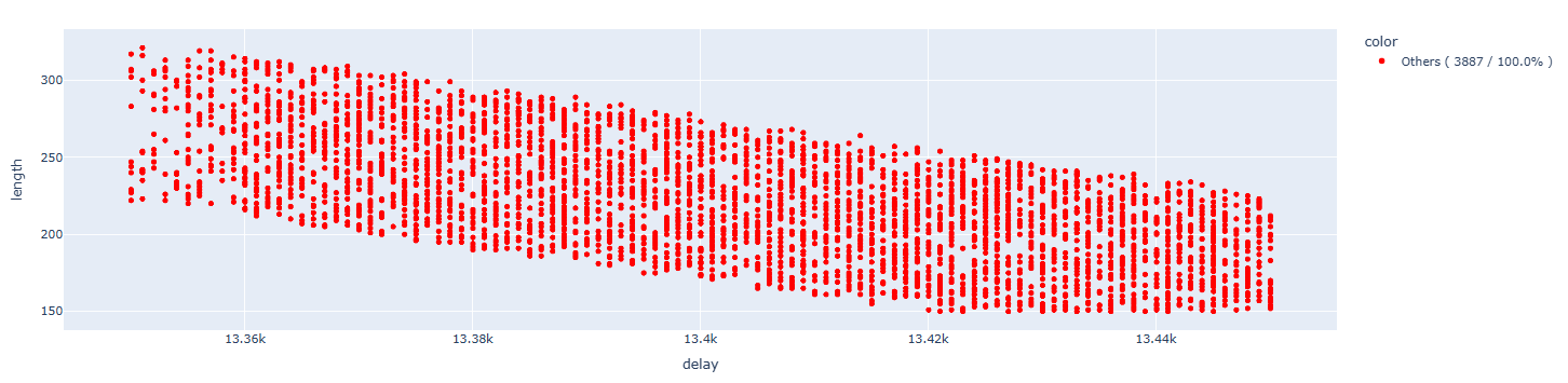
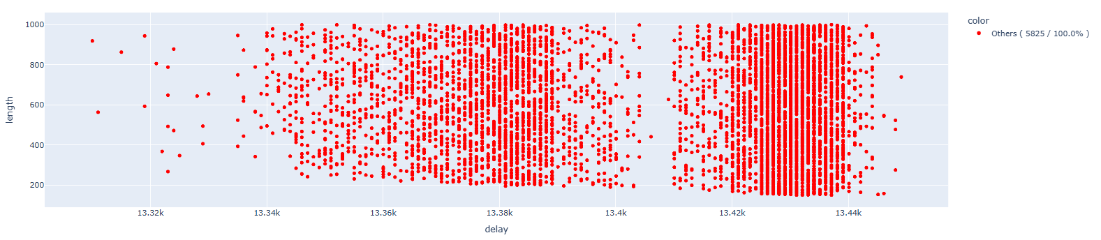
Let’s clean up the results, focusing on those that interest us:
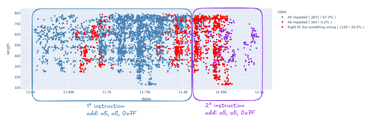
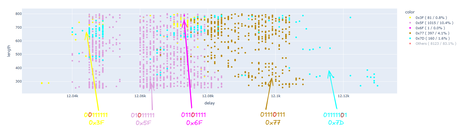
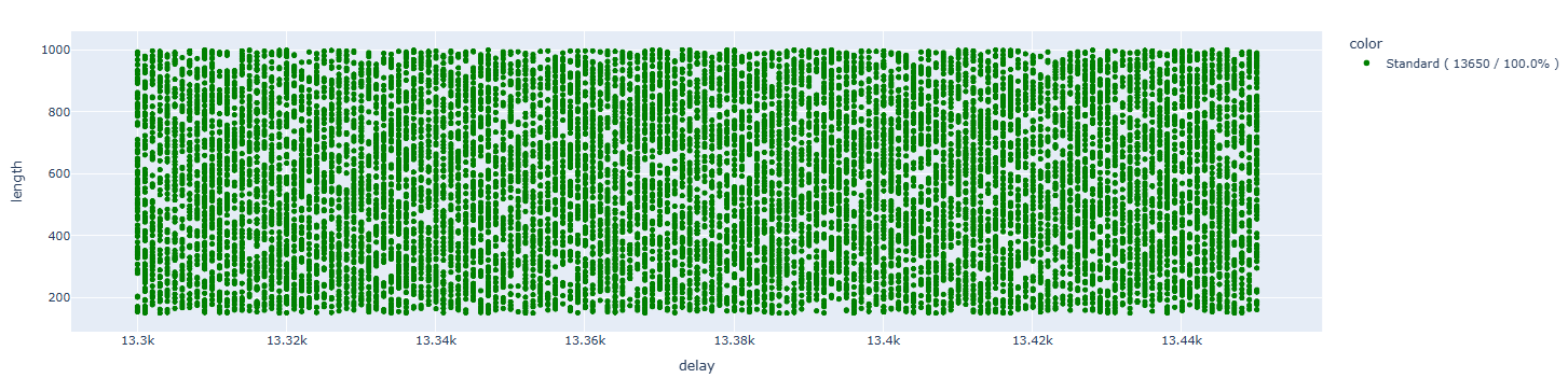
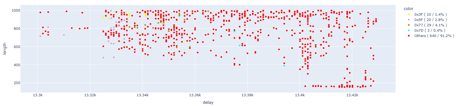
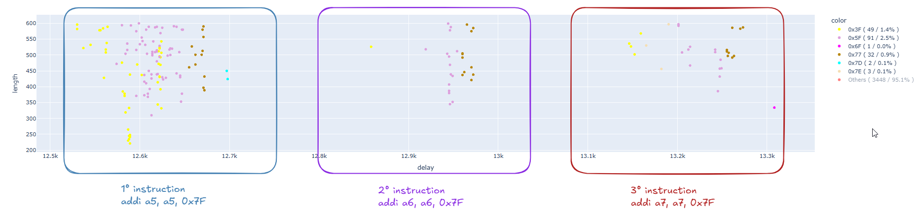
Let’s now change the data we plot. We are interested in the content of the A5 register. Therefore, let’s plot the content of this register in our runs (we are only interested in single bit flips – the label “other” refers to changes in more than one bit):
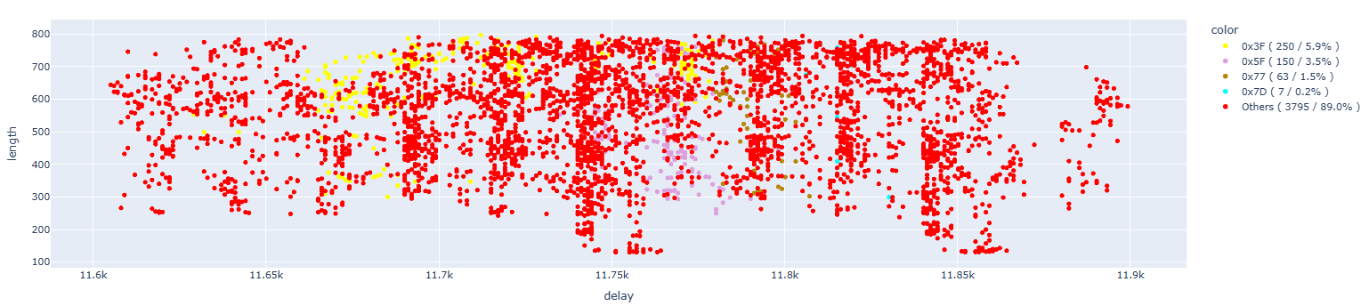
As we can see, we found many single bit flips that caused the content of A5 to become 0x3F, 0x5F, 0x77, and 0x7D, while we did not manage to get examples of the other four possible values (0x7F, 0x6F, 0x7B, and 0x7E). For convenience, we remove the points where more than one bit has been changed:
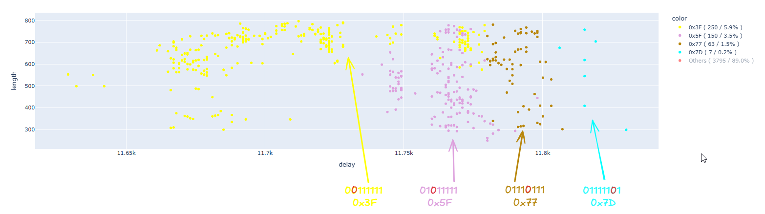
We need to consider a possible anomaly with the first value, which is 0x3F. Since the changed bit is the first in a series of 1s, we cannot be sure that our glitch only changed that one bit, because our glitch might have also changed two consecutive bits, the first and the second. Unfortunately, since the first bit is already 0, we cannot be certain. For this reason, we must treat this case as special.
In the image, it is possible to infer a clear correlation between the changed bit and the time at which the glitch occurred.
Based on my mental model, I would have expected a direct correlation between the duration of the glitch and the number of bits changed, but my experiments seem to go in a different direction…
Let’s now check if the behavior of glitches on subsequent instructions is consistent or not:
_addi a6, a6, 0x7F
The results are:
Removing the uninteresting results:
In the case of the second instruction, we have results similar to the previous case: we managed to induce a fault in a single bit.
To be sure, let’s also check the last instruction:
_addi a7, a7, 0x7F
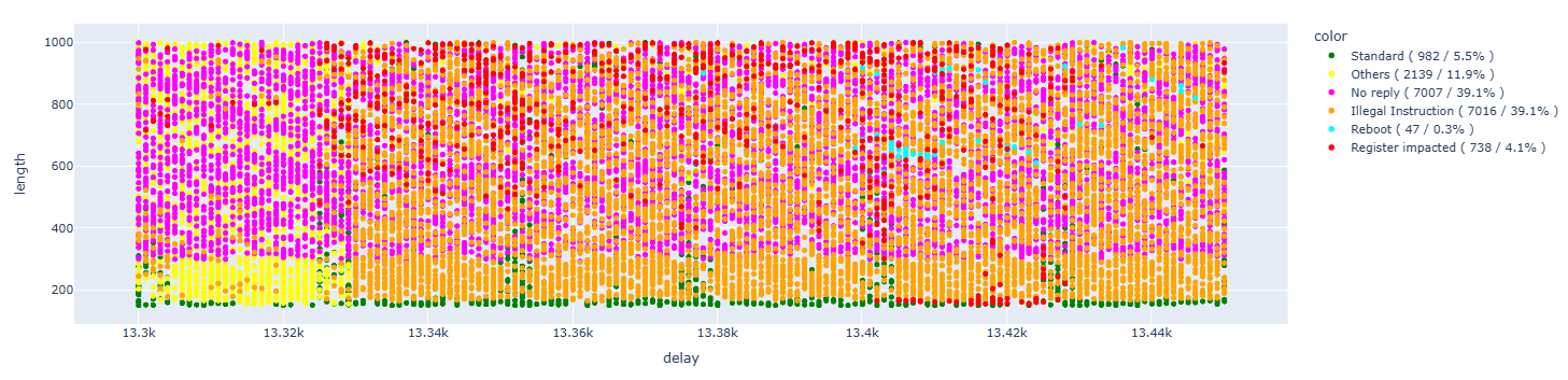
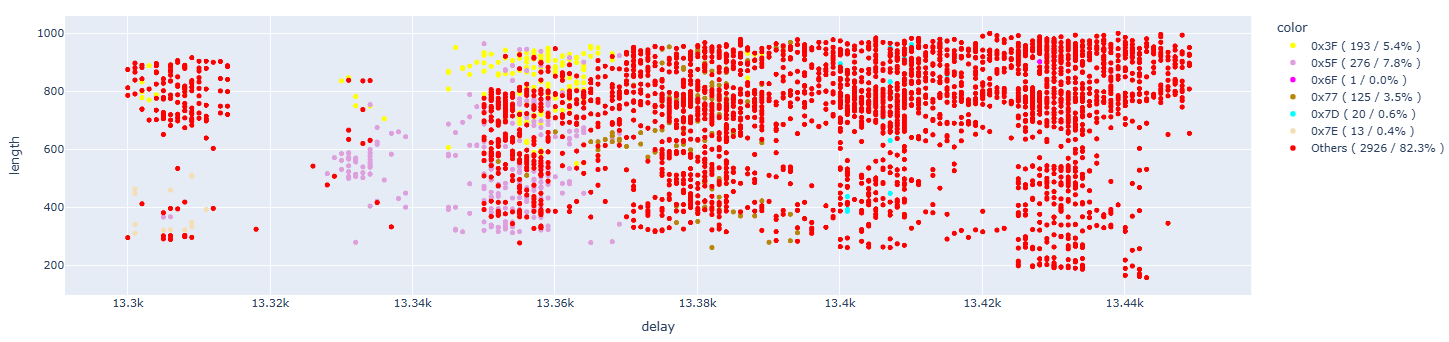
The results are:
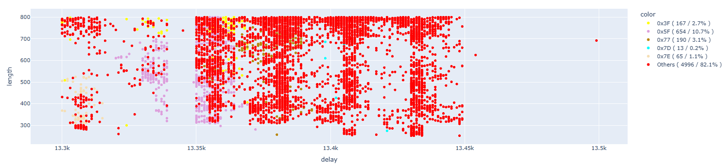
Removing the uninteresting results:
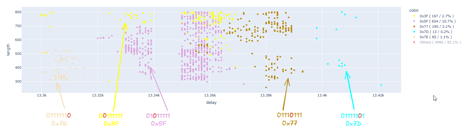
In this case as well, the results are similar to the previous case: we demonstrated the possibility of inducing flips on individual bits, and the impacted bit is directly correlated to the glitch delay. However, there is an anomaly with the value 0x7E, which appears before all the others, whereas it should be the last one.
In any case, the tests conducted allow us to state with certainty that it is possible to perform a fault injection on a single bit. However, it is likely that some bits are “easier” to flip than others, as some values appear less frequently in our results.
Trying to get better results
Having reached our initial goal, I wondered, is it possible to achieve better results? Can we find a setup that would allow us to reach our objective more quickly?
Let’s revisit the previous diagram that explains the power domains of the processor:
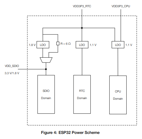
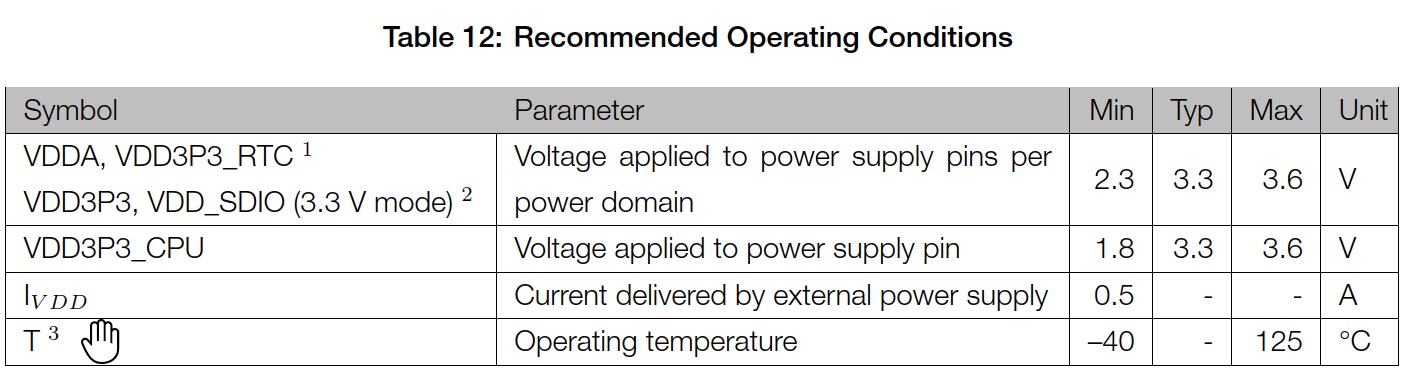
In the technical documentation, we can see that the pins support different voltages. In fact, VDD_CPU has a minimum voltage of 1.8V, while VDD_RTC supports a minimum of 2.3V:
At this point, let’s try different voltage values to determine what works best, trying to glitch only on one of the two VDD inputs we attacked before (VDD_CPU from VDD_RTC) while leaving the other stable.
For convenience, let’s focus on the last instruction, for which we already know the offsets. We’ll try various voltages, limiting to those that ensure that the software functions correctly.
Case 1 – VDD_RTC stable – Glitch on VDD_CPU 3.3V
In this case, the tests were conducted with the following setup:
- VDD_RTC stable with 3.3V
- VDD_CPU with separate power supply on 3.3V and GLITCH
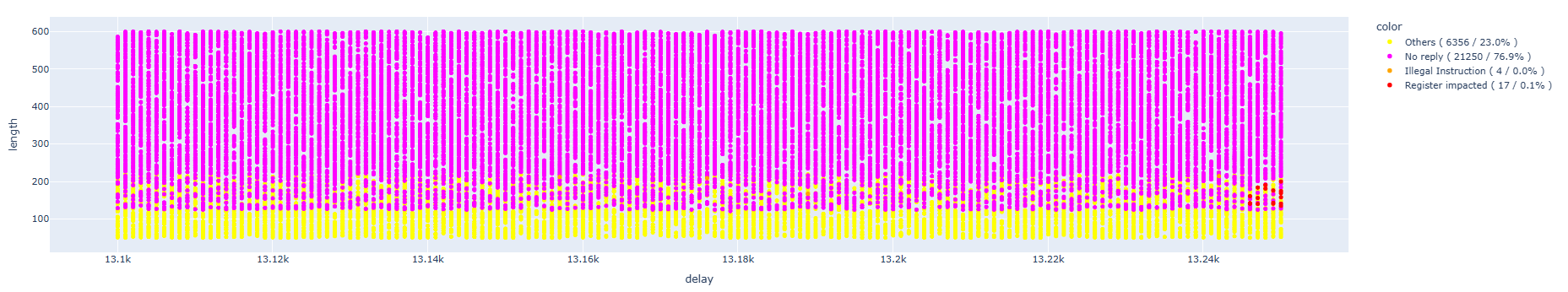
For all the following images, we will try to identify both the errors provided by the CPU and, most importantly, the case of interest for us, which is when the content of register A7 is altered, specifically altered in a single bit:
We can see that the results appear to be much more linear that before:
Analyzing the results of interest, we notice that we don’t have any specific single-bit outcomes. All the results correspond to the same value. We do not know the reason for this fact. However, it is unusual that in all the faults the content of A7 is always the same:
A7 : 0x00000023(0x0000007f) - 00100011
Case 2 – VDD_RTC stable – Glitch on VDD_CPU 2.0V
Let’s now try the same scenario as case 1 but with a lower voltage (2V).
The tests were conducted with the following setup:
- VDD_RTC stable with 3.3V
- VDD_CPU with separate power supply on 2V and GLITCH
Cleaning up the results:
Also in this case, as in the previous one, theres is no sign of single-bit faults.
Case 3 – VDD_RTC stable – Glitch on VDD_CPU 1.8V
Let’s now try to further decrease the voltage of VDD_CPU (1.8V), while still leaving VDD_RTC stable.
The tests were conducted with the following setup:
- VDD_RTC stable with 3.3V
- VDD_CPU with separate power supply on 1.8V and GLITCH
In this case, we’re unable to induce any fault. All executions complete successfully.
We hypothesize that this happens in the opposite way compared to what occurred in cases with higher voltages because the LDO regulator behaves differently below certain thresholds, but these are just hypotheses.
Case 4 – Glitch on VDD_RTC + VDD_CPU 3.3V
Let’s now come back to our initial test case (glitch on both VDD_RTC and VDD_CPU), but this time using 3.3V.
The tests were conducted with the following setup:
- VDD_RTC and VDD_CPU with separate power supply on 3.3V and GLITCH
Cleaning up the results:
In this case, as we have already experienced in previous tests, we are able to cause faults even on single bits. Analyzing the details, we have about 9% of single bit faults. Considering that we’re working on a 4% subset of full results, this means we have 0.36% of single bit faults.
Case 5 – Glitch on VDD_RTC + VDD_CPU 2.52V
Let’s now continue with our initial test case (glitch on both VDD_RTC and VDD_CPU), but this time lowering the voltage to 2.52V.
The tests were conducted with the following setup:
- VDD_RTC and VDD_CPU with separate power supply on 2.52V and GLITCH
Cleaning up the results:
In this case, as we have already experienced in previous tests, we are able to cause faults even on single bits. Analyzing the details, we have about 18% of single bit faults. Considering that we’re working on a 6.6% subset of the full results, this means we have 1.2% of single bit faults.
It looks like the best setup is indeed the one we initially chose, which is to perform the glitches on VDD_CPU + VDD_RTC at a minimum voltage that allows the processor to function correctly.
Case 6 – Running at 160Mhz
Beside searching for the the best VDD input line and the best voltage value, we can also try to see if changing the processor speed may improve our glitching results.
Until now, we used the 80Mhz processor speed which is the frequency at which the ROM code and the bootloader are also executed. Now, let’s change the speed to 160MHz and see what happens.
With the increased speed, the processor will have higher power consumption, so the initial voltage will also be higher than before. In this case, we found that going below 2.60V results in an unstable situation. Consequently, we will use 2.60V:
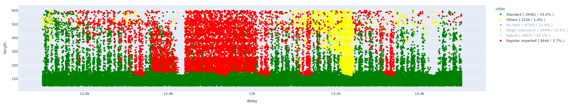
Cleaning up the results:
In this case, we also managed to obtain results that allow us to identify the modification of a single bit in areas similar to those already identified. Below, we can observe these areas for the three different instructions, after data cleaning:
Certainly, it is not comparable with the previous data (earlier we focused on a single instruction), but we have about 5% single-bit faults, which is lower than the previous percentages when we were running at 80MHz.
However, we have confirmation that even though it is more challenging, we can still perform single-bit faults at 160MHz without too many problems.
Case 7 – Running at 240Mhz
Let’s try to increase the processor speed to 240Mhz.
As previously observed, to make everything work at this higher speed, we need to further increase the voltage up to 3.1V:
From what we have observed, the behavior is different at 240MHz and we are unable to achieve single-bit faults. In fact, we only managed to get a few faults that impact the A7 register, in which case the content of A7 is always the same:
A7 : 0x00000023(0x0000007f) - 00100011
We hypothesize that when the processor operates at 240MHz, the power consumption is higher, making it more difficult to induce faults without causing the processor to restart.
Conclusions
So, what have we learned from these experiments? That sometimes unicorns exist! The possibility of performing a glitch that leads to the modification of a single bit is definitely real at 80Mhz and 160Mhz. We can glitch with precision, without glitching and praying, trying to “skip one instruction” (which means only that something that we haven’t understood has happened…).
From the tests carried out, we were able to observe how some bits are easier to influence compared to others. For example, we were never able to flip the 6th bit (01111011 – 7b) and we flipped the 4th bit (01101111 – 6f) only a few times, while the others were flipped multiple times.
Performing glitching exclusively on VDD_CPU, at least in this case, does not improve the situation. In fact, the results are much worse. The presence of the LDO (low dropout) regulator has a significant impact in this scenario. An important takeaway from this test is that the lowest voltage is not necessarily the best one. In fact, no faults were generated at 1.8V.
In the tests performed on VDD_RTC and VDD_CPU together, however, a significant increase in faults of interest can be observed at the lower voltage compared to the standard 3.3V situation.
From the analysis of some results, I realized that it is also possible to cause glitches that modify the value in a “non-continuous” way. To date I cannot hypothesize what the logic could be… However, I have observed, for example, the following results:
StoreProhibited - PC: 0x400d7125 - A5 : 0x00000057(0x0000007f) - 0101 0111
StoreProhibited - PC: 0x400d7125 - A5 : 0x00000017(0x0000007f) - 0001 0111
Many things still need to be understood and explained in this realm, see you next time!